Ads

Saturday 19 December 2015

Super cheap 3D printer start from scratch!!! (Part 3 - Add your LCD!)


Finally, successfully install this LCD to my 3D printer!! Initially it cannot function and blamed as  I thought I had bought a malfunction RepRapDiscount Smart Controller since it was from China. Buzzer sounded non-stop and SD card cannot be detected.
But then after searching on internet and it proved that I am the one who should be blamed! Hahaha. Anyhow, lets do the serious matter first. So if you are using Marlin then you have to modify your code. It wont take too long.

GADGETS3D_shield_main2
(http://reprap.org/mediawiki/images/9/9a/LCD1.png)
LCD2
(http://reprap.org/mediawiki/images/6/6c/GADGETS3D_shield_main2.jpg)

Marlin V1 (new)

In "Configuration.h”
  • Change line 46 to #define MOTHERBOARD 33
  • Change line 306 to #define REPRAP_DISCOUNT_SMART_CONTROLLER (just remove the // at the beginning)
  • Change line 326 to #define NEWPANEL //enable this if you have a click-encoder panel (just remove the // at the beginning)
Switch over to "Pins.h" and change line 318 to #define RAMPS_V_1_3 (just remove the // at the beginning) And, good luck!!


Wednesday 25 November 2015

Super cheap 3D printer start from scratch!!! (Part 2)

REPRAP schematic.png
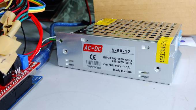
Finally!! Just want to let you all know, nothing can be done if you dont try it!! Hurray! After wasting 4 days I knew that what is the problem! Power source, Yes. You should use a power source with 5A rating or it might not run properly.
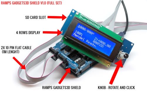
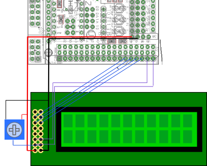
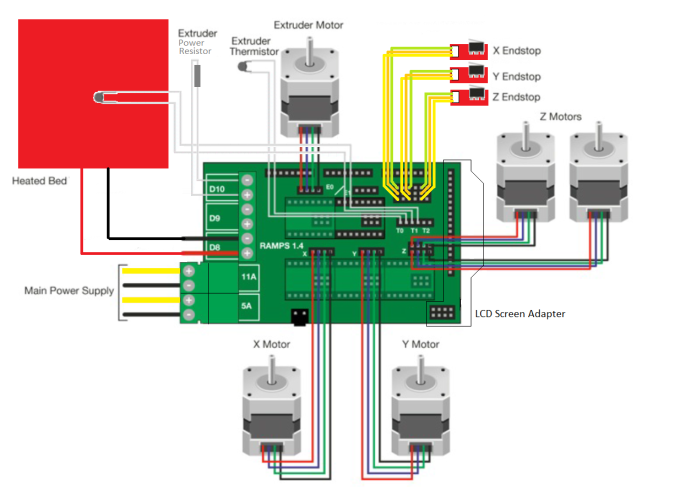
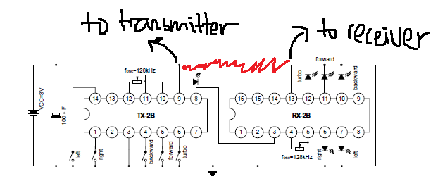
Start with the wiring parts, what you need to do is just refer to this figure:


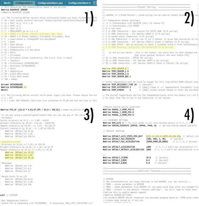
THEN, let's start the firmware setup/modification one by one. first of all, kindly download Marlin firmware from Github(https://github.com/MarlinFirmware/Marlin). After downloaded the file, extract it and open the Marlin folder. Try to find Marlin.ino which required Arduino (http://arduino.cc/en/Main/Software) to open it.
F8Q264UI236HE61.LARGE.jpg

Configuring and compilation

What you need to know before starting:


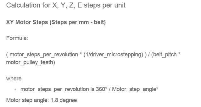
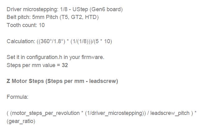
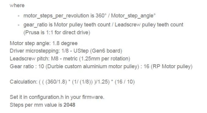
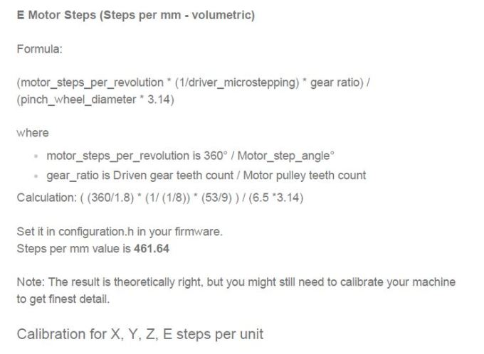
  • What kind of printer you are using. If you are using a Cartesian printer (like the Prusa i3), you are going to need to calculate the steps/mm for each axis and for the extruder. To figure this out, you can go to http://prusaprinters.org/calculator/ or Triffid_Hunter's_Calibration_Guide. Write down the values you get for everything.
    • You need to know what kind of drive is being used with your printer. If it's a belt, you need to know what kind. If it's a screw, need to know what kind.
    • The Prusa i3 uses belts for X and Y, and screws for Z.
  • A host software like Printrun or Repetier or even Octoprint.
  1. Install the arduino software IDE/toolset, version 1.0.5 or 1.0.6 from http://www.arduino.cc/en/Main/Software
  2. Download the Marlin firmware from https://github.com/MarlinFirmware/Marlin (see the Download Zip button), or use git to clone it (if you know how to use git).
  3. Extract the firmware to a directory of your choice.
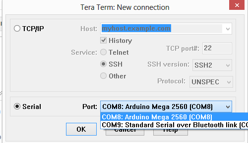
  4. Start the arduino IDE. Select Tools -> Board -> Arduino Mega 2560 (or whatever your microcontroller is)
  5. Select the correct serial port in Tools ->Serial Port, usually there is only one option.
  6. Open Marlin.ino in /path/to/Marlin/Marlin
  7. Browse to boards.h
    1. This is a list of motherboard types. You'll need to figure out which one you need and write down the word after #define on that line.
      • Example: If you're using a RAMPS 1.4 with a extruder, fan (optional) and heated bed, then you'd need RAMPS_13_EFB.
  8. Browse to Configuration.h
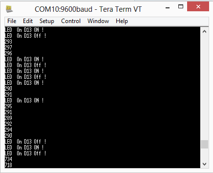
    1. Write down the value given in #define BAUDRATE for later.
    2. At the line that says #define MOTHERBOARD, replace whatever follows MOTHERBOARD with what you chose earlier.
    3. Set the #define EXTRUDERS to the number of extruders that you have.
    4. For the TEMP_SENSOR lines, you have to know what kind of thermistor is used by your hot end and heated bed (if you have one). Set the values for these to ones that match the list directly above the lines.
      • If you have an extruder on E0 and a heated bed, you just need to set TEMP_SENSOR_0 and TEMP_SENSOR_BED.
    5. Scroll down to MAX_HEATER_TEMP. If you know that your hotend shouldn't go above a certain value (the Budaschnozzle should not exceed 240C-242C), then change it here. Same for MAX_BED_TEMP.
    6. Leave the PIDTEMP stuff alone for now, we'll get back to it later.
    7. Further down the page, look for the Mechanical Settings area.
      • For the INVERT_X_DIR and related lines, set it for Mendel if you are using a Mendel-type printer. Otherwise, consult the documentation for your printer design.
      • For X_HOME_DIR and the similar commands for Y and Z, look where your endstops are. If a endstop is configured to be at the 0 position for that axis, the setting here needs to be -1. Otherwise, it needs to be 1.
      • The X_MIN_POS, X_MAX_POS, and related entries should correspond to the printable area on your bed. The defaults are common, but if you have a bigger/smaller print area, you will need to change this.
        • Please note that 0,0 should be the cartesian "bottom left" of your print-bed, if your axis homes beyond the bed in any direction, you can use a *negative value* for the X_MIN_POS and Y_MIN_POS to compensate. (If your prints never wind up in the center of the bed, this is the culprit). Also See Configuring Marlin Bed Dimensions.
      • Ignore the auto bed leveling area for now. Hopefully you will never need it.
    8. Time for the Feed rates and Steps/mm! You're almost done.
      • For #define DEFAULT_AXIS_STEPS_PER_UNIT, you will need to use the values you calculated for your different printer axes and extruder (see above). The order is {X, Y, Z, E}
      • For DEFAULT_MAX_FEEDRATE, this is the fastest (in mm/s) the printer is allowed to go.
        • For a Prusa i3, setting the Z axis value to 2 is a good idea.
      • DEFAULT_MAX_ACCELERATION is something else that should be tuned based on how good you built the hardware of your printer.
      • You should probably turn DEFAULT_ACCELERATION to a lower value initially (like 200) and adjust the acceleration later once you get everything calibrated and tuned.
    9. If you have an LCD or button panel for your printer, uncomment the respective lines for it. Otherwise, save because you are done!
  9. Click the Upload button.
    • If all goes well, the firmware has uploaded.

Capture
Capture1
Capture2
Capture3
Finally, just insert/replace the value you had calculated into here:
Capture4
DONE!! Upload your programming to Arduino and test it now!
Power up Arduino and connect it with Repetier host. The rest I just leave it to you, GOOD LUCK!
Repetier Host: http://www.repetier.com/download-software/


After X and Y axis were fixed, I try to draw something using Repetier Host software to confirm the axis were well calibrated.


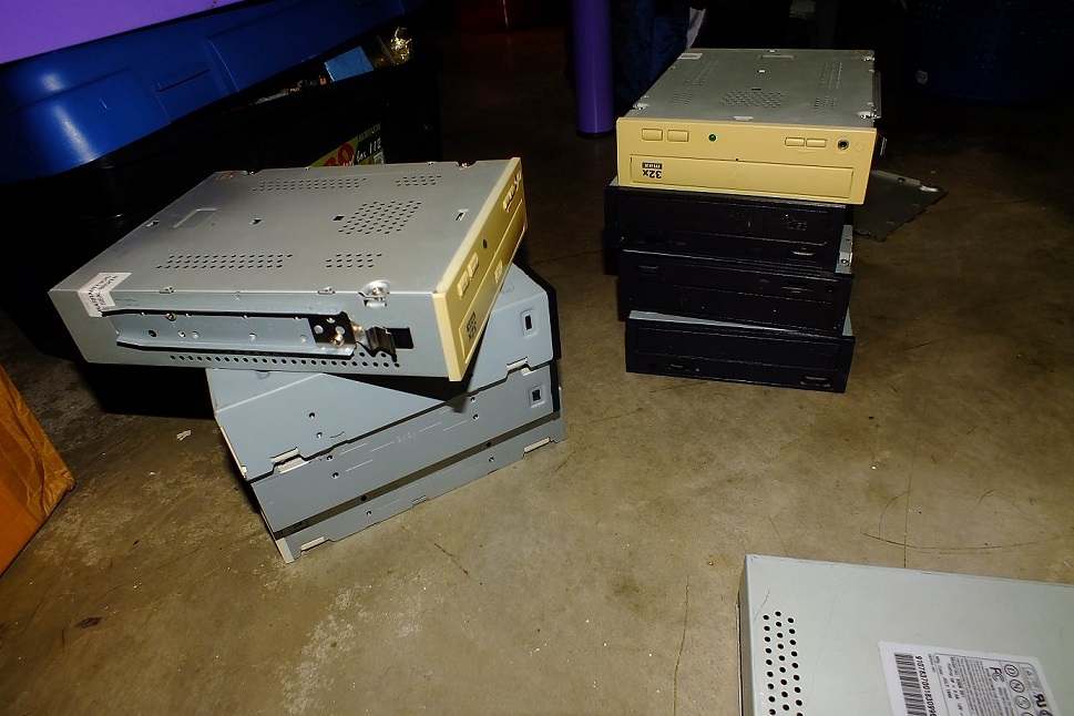
Then did the Z axis! Since every parts was DIY, it seems.... Hrm, as long as it can use, no problem right?! Going to make it bigger like 25x25x25 cm^3 after I gather the Canon M-series printer parts.
DSCF0152
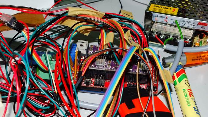
Remember to tidy up the cables and give them a tag!!
DSCF0171
Buy a power supply up to 12V 5 A or I think it could hardly work for you! Trust me!


Finally make a small "house" for the power supply and those microcontroller. It need the fan for long term use, dont forget!
If you interested in doing this cheap 3D printer can pm me!! (https://www.facebook.com/Arduino-wholesale-Msia-only-1701856016767472/?ref=aymt_homepage_panel)

Saturday 14 November 2015

Super cheap 3D printer start from scratch!!! (Part 1)

DSCF0003
cd drivers from EE school
DSCF0004
I spend 10 minutes to open it up

Super low cost DIY 3d printer from e-waste! It's been a long day when I planned to do this since the materials' price list from internet is too heavy to me. Besides, dont really have the time to do this as I thought my days were that busy. Until I finish the whole thing, I realized that "BUSY" is just an excuse. We still have the time to get enough sleep and eat or even uses Facebook up to 2 to 3 hours per day right? If you are using Facebook to earn money like me last time, I dont have anything to complain, but, if you just wasting your time scrolling every single post, damn it, you should give me your time. As in the end, I will still appreciate your sacrifice XD
Sincerely, we dont really have much time to be wasted.
DSCF0022
1 hour of work
I admired the designer/engineer of this kind of drives, and also the engineers whom assemble these part. In order to reduce the damage on it, I almost spent an hour to completely dissemble one drives!

Saturday 31 October 2015

Gunung Lipur, Hiking !!! (2016/10/31)

The road not taken, huh?
Well, it was a very long long time since my last hiking with form 6 friends. Missing this kind of activity badly as it is quite challenging but somehow dangerous. The main point is not who is/are your partners, but the target/goal you set for yourself, like "I must finish it" or "I will stop if i really could not move anymore". But for me, the latter cannot be counted as GOAL right?

IMG_20151101_100756
So, asphalt road or "mountain" road? We took both.
Challenge yourself while you are young and your
heart still burn in fire!!!


Tired, huh? I am the one with singlet.

Thursday 8 October 2015

Arduino + Bluetooth module HC05, Serial Communication With LAPTOP? Simple!

Connect Bluetooth module to laptop is quite easy, because there are many open source software available on internet now. If we want to send or receive Data between Arduino and computer, firstly we need to make a Communication link to Definition Arduino Board to the computer. A software called Tera Term to show the data received or what we want to send through it. You can get the software here:


(https://en.osdn.jp/projects/ttssh2/releases/) Arduino support something Called Software Serial , which allow You to change any arduino board pin to serial pin. http://arduino.cc/en/Reference/SoftwareSerial To link your bluetooth module with laptop:
  1. power up HC-05 using Arduino
  2. for Windows user, go to control panel and "Add Device"
  3. the default password for HC-05 is "1234"
  4. after pairing up, you can compile and upload the code to Arduino
  5. sometimes you may fail to upload the program to Arduino board. Try to disconnect or turn off the bluetooth module while uploading the problem. After that, connect or power up the bluetooth module again.
  6. Open Tera term software (have to install it first from the link above), go to file > new connection. From the pop-up window, choose "serial" and related serial port.Screenshot (49)
  7. Congrats, you have done!
Here is my result:
Capture

Thursday 17 September 2015

Best friend? Once.

He was my best "new" friend, once. We met two year ago, and he was like a "big" brother to me, and we talked about anything, which I thought this condition or fate was endless, before I decided not to be that "nice" with him.
I still cannot figure out, the more the efforts i tried to help, the more he blamed on me. Seems like everything I did before go in vain. I taught, spent my time, and even my interest, finally he thought or showed me that, "you are my good friends if and only if you stand by my side, make or treat my defects as my strengths, do everything I ask you to do without any grumble....".
The saddest thing in one's life is, the one you care is not care for you, the one you help does not think or thank for your help, the one you love showing off his/her happiness with partner. Yet, I knew that every problem arises because of one self. You were betrayed because you choose to believe in someone, you fall in love because you give yourself the chance or persuade yourself to give in......
To me, I do not have a best friend, and I do not wish to be a best friend of someone, as I do not want to betray anyone. This is the life I knew earlier, and I decided to be indifferent to everything around me and anyone I met, except my family.

Thursday 3 September 2015

RF 315/433 MHz Transmitter-receiver Module without Arduino? Sure!!

DSCF0075
4 Channel RF transmitter + receiver
How to connect this wireless RF module and operate without Arduino? It is POSSIBLE??  I found this way out of sudden, you could say that I am to bore to try everything I bought from China as all stuff just too cheap, made me dare to try without second thought. Yet, the shortcoming was that, since it is non-programmable, it is actually works like sending a "HIGH" and "LOW" through radio wave, that means no analog control!!
Untitled
Schematic
The most important thing you need is encoder and decoder. For my case, I used RX-2B and TX-2B IC.Just follow this schematic and everything will work. You can also use RX-5B and TX-5B if you want more than 5 channels. Consumed about half an hour to finish this. It can be seen that 2 IC on the receiver side. the left side is RX-2B, right one is L293D, I made this purposely so that I could use on rc car, where forward and backward can be done by connect the motor to L293N directly. MultiPURPOSE!! Lastly, remember to adjust the trimmer on receiver side so that it receives signal from transmitter!  
DSCF0072
Receiver tonel board
DSCF0069
Receiver and transmitter
Shoud I make an Instructable?